 Column Splice Settings
- General Overview
- Tips and Tricks
- Related Tools
Flange splice plate clearances
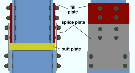
| Connection design adds a fill plate to make up the difference between the depths of the spliced sections and leaves a gap between the splice plate and fill plate. This gap is the field clearance and must be at least 1/16 of an inch. The following settings control that field clearance and also set the thickness of the fill plate. |
|
| This applies to any column splice with two W, S, or welded plate sections of unequal depth. |
Upper shaft minimum field clearance: The minimum clearance that you want connection design to leave between the upper fill plate and the splice plate (or the upper column and the splice plate if there is no upper fill plate).
If the upper column is less deep then the lower column, this sets the clearance between the upper fill and the splice plate. If the upper and lower column are the same depth, this sets the minimum thickness of the lower fill plate .
Upper shaft maximum field clearance: The maximum clearance that you want connection design to leave between the fill plate and the splice plate (or the upper column and the splice plate if there is no upper fill plate).
If the upper column is less deep then the lower column, this sets the maximum clearance between the upper fill and the splice plate. If the upper and lower column are the same depth, this sets the maximum thickness of the lower fill plate .
Lower shaft minimum field clearance: The minimum clearance that you want connection design to leave between the fill plate and the splice plate. This only applies if the depth of the upper column is greater than the lower column (click here for an example).
Lower shaft maximum field clearance: The maximum clearance that you want connection design to leave between the fill plate and the splice plate. This only applies if the depth of the upper column is greater than the lower column (click here for an example).
Inner flange plate
Use inner flange plates: ![]() or
or ![]() . This instructs connection design to design inner flange plates at column ends when " Inner flange plate " is set to
. This instructs connection design to design inner flange plates at column ends when " Inner flange plate " is set to ![]() Connection specifications " on the Column Edit window. It applies to AISC connection design methods .
Connection specifications " on the Column Edit window. It applies to AISC connection design methods .
|
|
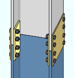
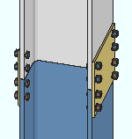
If this box is checked (
), connection design attempts to design inner flange plates for ' All-Bolted plates ' splice connections. The length of the inner flange plates is equal to the length of the outer flange plates. Where necessary, connection design adds inner flange fill plates to make up the difference between the inside surfaces of the lower column flanges and the flange plates.
If this box is not checked (
), connection design does not design inner flange plates for bolted splice connections.
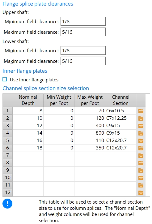
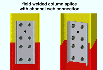
Channel splice section size selection
| To determine which channel to use , connection design looks at the entries made to the table that is explained below. |
|
| Nominal Depth | Minimum Weight per Foot/Meter | Maximum Weight per Foot/Meter | Channel Section |
| The " Nominal depth " of either column. Both columns must be the same section size for connection design to create this type of connection. | The minimum weight per unit distance of the columns that the "Channel Section" will splice. | The maximum weight per unit distance of the columns that the "Channel Section" will splice. | The channel splice used when the values reported in this row match the " Weight " and " Nominal depth " in the local shape file for the columns being spliced. |
| Note 1: This applies to wide flange, S shape, or welded plate W columns only. | |||
| Note 2: Connection design looks at the section sizes of the columns being spliced and compares the values on this table with the " Weight " and " Nominal depth " values in the local shape file in order to determine what channel section to use for the splice. | |||
| Note 3: To specify that a channel web connection be designed on a column, check the box for " Channel web connection " on the Column Edit window. | |||


|
|
OK (or the Enter key) closes this screen and applies the settings.
Cancel (or the Esc key) closes this screen without saving any changes.
Reset undoes all changes made to this screen since you first opened it. The screen remains open.
- Channel (type of material entered on this table)
- Column splices (connection type this window sets up)
- Setup for column splice connections (index)
- Connection material specs for channels (sets steel grade)

